A few months ago we welcomed an Ironman in our office that very quickly became a valuable member of the team. While it looked pretty cool, we wanted to add some “spice” to it.
So I came up with the idea to add a glowing heart to it – an indicator which would change colors under certain conditions. After a short discussion with the team, we chose to make that condition the status of the Internet connection in the office.

As we occasionally may have internet interruptions at the office, it would be great if the team could see the current connectivity status, so that in case of an outage we could contact the provider immediately and tell him what kind of problem we have without even opening the monitoring services. That is why I decided to visualize the quality of the Internet connection with the help of an indicator.
ESP8266 project
I chose to use a bulb with different colors as an indicator, and since I had an RGB stip, that was the best choice. The main part of the project was the controller with PWM (Pulse Width Modulation) that allowed changing colors of the indicator. As the RGB strip (as well as the single RGB LED) had 4 pins (the colors red, green, and blue and common contact, +/- depending on the type of RGB LED), I needed the controller to manage the colors. It was important that the controller had a wireless connectivity. For this I chose the ESP8266 WiFi module, a highly integrated chip designed for the needs of the IoT (Internet of Things). I used ESP8266-07 modification, because it had enough GPIOs (General-purpose input/output pins) for connecting to the RGB strip. Also, ESP8266 IoT is more powerful in general than Arduino and has more ROM and RAM, but is smaller.
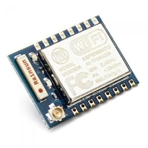
The IoT chip I bought had the following characteristics:
- CPU Frequency: 80MHz
- Flash size: 512K (64 SPIFFS)
- RAM data: 80K
- RAM instruction: 32K
- GPIO: 16
The next step was to select the Firmware for that chip. There are several types of firmware for IoT available for this chip, such as native AT mode, NodeMCU, Smart.js and Arduino IDE. The last one is more familiar to me, so I’ve chosen Arduino IDE for the IoT project.
After that I needed to assemble the scheme to be able to flash it with my code.
The electronic parts that I used for it were:
- Power adapter 12DC – 1pc
- IoT chip ESP8266-07 – 1pc
- Breadboard – 1pc
- Connectors for breadboard ~ 20pcs
- DC-DC adapter 12v to 3.3v – 1pc
- Resistor 10K – 8pcs
- Resistor 4.7K – 3pcs
- Resistor 2.2K – 3pcs
- Transistor MOSFET STP16NF06 – 3pcs
- Transistor bipolar BC547B – 3pcs
- A part of RGB strip
- Any USB-TTL adapter for flashing
- Resistor 220 – 3pcs (for debugging)
- RGB led with common anode – 1pc (for debugging)
The scheme had 12V DC power for the RGB LED strip, and 3.3V for ESP8266, so I needed an additional step down converter from 12V to 3.3V. I used a DC-DC converter based on LM2596.
DC-DC converter based on LM2596To control LEDs with ESP I used cascade of MOSFET and a bipolar transistor for each channel. As the first step I had to connect all necessary pins of ESP for uploading firmware via Arduino IDE (as it is shown on the scheme below). It is important to mention that GPIO0, GPIO2, RESET, EN should be pulled up and GPIO15 should be pulled down for the stability of the chip. Then I connected ESP to PC via the TTL-USB adapter.
I had some trouble with PWM, because I had only MOSFETs STP16NF06, N-channel 60V, 16A. ESP gives only 3.3V of control signal and that is not enough for the power transistor to work steadily, so I had to enhance the level of signal for the Gate. For this the additional NPN transistor BC547B was used, which pulled up the Gate of MOSFET to 12V and changed the logic to inverse for GPIO12 ,14, 16. It is important to mention that this method has a disadvantage; the LEDs are always turned on even when ESP is off.

Step 1: The hardware part
I started with building the circuit on the solderless breadboard as shown on the project scheme above. ESP is shipped with AT-command firmware, so I had to first set up the last version of the Arduino IDE with all necessary libraries, as described in the Arduino IDE manual. At the first stage of debugging I used a simple RGB LED instead of the cascades of transistors. It’s important to use an LED with a common anode, which is with common VCC, otherwise it will work in a reverse mode. After that, each LED pin must be connected to GPIO16, 14, 12 accordingly via 220ohm resistor.
Now when I had the circuit assembled, in order for it to work correctly, I had to prepare the software part which consisted of firmware for ESP and the server side script.
Step 2: Sketch for ESP
To prepare the environment to build and upload the sketch to the chip, I connected the full circle to the power and to the USB port via the adapter, opened the Arduino IDE with pre-installed libraries, downloaded a sketch for ESP from github, and set the right ssid and password in the arduino sketch.
for ( uint8_t i = 0; i < server.args(); i++ ) {
		message += " " + server.argName ( i ) + ": " + server.arg ( i ) + "\n";
		int tmp = 0;

		if (server.argName(i) == "rgb" )
    		{
      			if ( server.arg(i) != rgb)
      			{
          			rgb =  server.arg(i);
          			convert(rgb, &message);
      			}
    		}
	}
Arduino sketch code on Github.
Next, I had to configure IDE correctly to work with ESP. The process was the following: I selected “Tools” -> “Board”, then “Generic ESP8266 module” from the list, changed the “Upload speed” to 115200 and selected the right “Port” with our usb adapter. Before chip flashing I had to press and fix the button on the circle named S2, connect GPIO0 to GND, and push S1 to reboot ESP. After that it was necessary to build and upload the firmware to the chip, and after a successful upload, to release button S2. Then I opened the Serial Monitor and pressed S1, the chip restarted and I was able to see the ip address of the chip from our network and the RGB LED changed the color to dimly white.
Step 3: Server side script
Now I had the work on device completed and could test it with a curl command such as:
curl ‘http://192.168.1.5/set?rgb=ff0000‘
curl ‘http://192.168.1.5/set?rgb=0000ff‘
in which “ff0000” and “0000ff” were the HTML code colors and the IP address I got from the Arduino IDE terminal console when ESP was restarted. After the first command the LED had to change its color to red, and after the second, to blue. When everything was ok, I started to prepare a script for monitoring the quality of the Internet connection.
def checkHost(host):

    global color

    ret = Popen("""ping -c 10 -i 0.2 -q -W 4 {0}| tail -n 2""".format(host[0]), shell=True, stdout=PIPE, stderr=PIPE)

    # Get packets lost
    try:
        lost = re.search(r'(\d+)% packet loss', ret.stdout.readline().rstrip()).group(1)
        if int(lost) > 20:
          if color < host[2]:
             color = host[2]
             print host[0] + ' ' + lost
    except:
        pass
The server side is on the Linux gateway. It’s a simple python script, that pings a list of servers every 15 seconds. Every host has 2 parameters: the maximum ping (max_delay) and the index of significance (color). When the ping to some host is more than “2 * max_delay” or packets lost are more than 20%, the quality of the connection is considered to be bad, and the script sends a post request to ESP with a parameter like ‘00ffff’ in order to change the strip color to one of the preset colors with fading. Each color represents the Internet connectivity status in range from “Ok” (good connection) to “Disaster” (full disconnection from the provider).
Troubles and fixes
During the project implementation I was faced with a number of problems. The first problem was that the signal was too weak to manage the powerful MOSFET, which I solved with the help of an additional bipolar transistor for signal amplification. The next problem was associated with the unstable work of the soft PWM with default settings, which I solved by changing the PWM frequency to 500HZ. The last issue, which is still unsolved, is with the high sensitivity to the static electricity that causes chip reboot.
The next step in the development was to move the scheme from breadboard to the textolite, and pull-up the rest pins.

Sum up
This project has already been working successfully for a few days, and during that time there was a small routing failure and as a result some services were not available for a few minutes. All my colleagues were able to identify what the issue was just by the color of the LED strip. And when the channel overloads and some pings are lost, the strip changes color to indicate the problem.
In general, I’m satisfied with the result, and later I can add more functionality since I have free GPIO and hardware resources.
I wish you a good hack!